
How to Create Layer 2 VLANs on NETGEAR ProSAFE Smart Switches
This guide will walk you through configuring VLANs on NETGEAR Switches that support VLANs. This guide is only for devices that have a web interface, and is not applicable to our Plus Series Switches, which use a software utility in most cases instead. Also it does not apply to older Legacy models, which used a different interface before the modern iterations.
What is a VLAN?
In a LAN environment, VLANs divide broadcast domains. This prevents Layer 2 traffic in one VLAN from accessing another, unless explicitly permitted to do so. When a host in one VLAN must communicate with a host in another VLAN, the traffic must be routed between them, using Layer 3 traffic. This type of routing is called inter-VLAN routing.
By default, a port is enabled for bridging rather than routing. With bridging, after an inbound packet is processed, the packet is associated with a VLAN. The MAC destination address of the packet and the VLAN ID are then used to search the Switch's MAC address table.
Steps
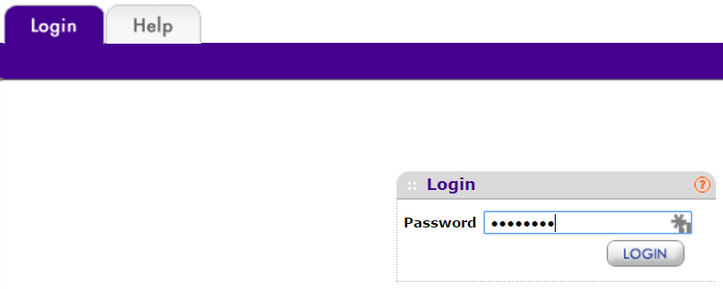
- Open a web browser, and login to the switch using the Management IP Address.
- First go to Switching, and then select VLANs, and lastly select Advanced.
- Under VLAN Configuration, there will be, depending on your Switch model, various default VLANs.
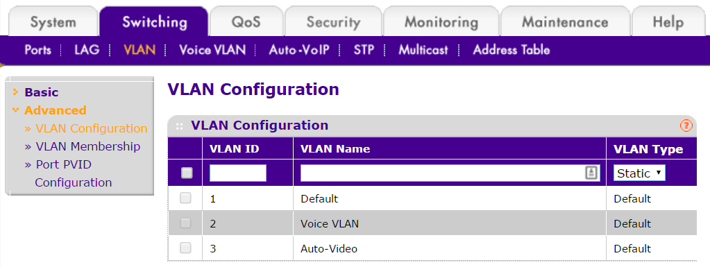
Important Note: By default, every port is a member of VLAN 1, which has a port VLAN ID (PVID) of 1. Not all NETGEAR switches support Tagging on VLAN 1. Check the user manual to be sure if it does. As it is the default VLAN, netgear does not recommend using VLAN 1 for anything other than switch administration. It is recommended to always have a complete network diagram of VLANs before setting up your network.
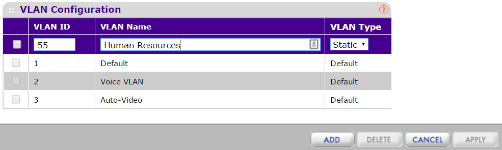
- Create a new VLAN, by choosing a VLAN ID between 4-4093(depending on what exists already), and name the VLAN appropriately.
Important Note: It is always recommended to have a complete network topology ready before creating a network, as VLANs generally will be passed across the network, and having a map and plan of all VLANs that will be needed is highly recommended before selecting and creating new ones. If there are existing VLANs that are numbered differently than the ones created for a similar purpose, then this will cause issues when trying to have the 2 network segments communicate.
- Once you have created and named all of your VLANs, we can move on to adding them to specific Interfaces.
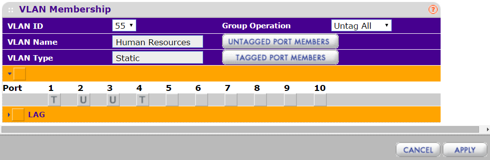
- Now go to VLAN Membership, and under VLAN ID, choose the VLAN you just created.
- Here you will see Ports and LAGs, which you can leave Tagged, Untagged, or blank(no participation).
- U, Untagged, means traffic is not tagged with the VLAN ID on Egress, when it exits the switch, to the next upstream or downstream device.
- T, for Tagged, means traffic is Tagged with that VLAN ID, and it will be preserved as it Egresses the switch.
- Blank, means that there is no participation for that VLAN, and that it will not Ingress, enter the switch, or Egress the switch at all, on that VLAN, from that port.
- Configure the Ports with the VLANs selected, respectively with how you want the traffic to flow through your switch, and upstream or downstream to other network devices.
Important Note: Some devices understand VLAN Tags, such as Access Points or IP Phones, but most personal computers do not. For example, if you have a VOIP Phone system, it might understand VLAN Tags. You would Tag the VLAN you have selected for that VOIP Phone system to each phone. Some phones also have a second NIC that connects to the respective PC nearby. For that Internet, or other PC VLANs, you would Untag the traffic for that port. Each port will have likely have a variety of different VLANs, based on the flexibility this provides.
- Lastly, we go to Port PVID Configuration, to configure the default Egress VLAN of the specific port.
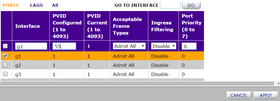
- For each port, although the default is 1, you can choose a different VLAN to be the default VLAN for that port.
- For example if you have a specific VLAN for Servers or Storage devices, you may want to change their default VLAN to be on the one you have set aside for that purpose.
Important Note:The default administration VLAN is VLAN 1 and if you change the port you are accessing the switch with to something other than the administration VLAN, you will lose access to the switch and need to factory default it. In order to regain access to the switch you can use another port has administration access to the switch, through VLAN 1.
Conclusion
It is highly recommended to test communication between multiple devices that have been configured, to ensure that traffic is passing and the configuration is correct. This is also why it is a good idea to have a complete topology, to cross-reference with if any issues arise during configuration.
Also bear in mind, that although Layer 2 VLANs can exclude other Layer 2 traffic based on configuration, in a routed network you would need Layer 3 ACLs to block networks from one another. Any other networks that you want excluded, would require a Layer 3 device, such as a ProSAFE Layer 3 NETGEAR switch, to block that traffic.